

Mercury vapor, light-emitting diode (LED), and excimer are distinct UV-curing lamp technologies. While all three are used in various photopolymerization processes to crosslink inks, coatings, adhesives, and extrusions, the mechanisms generating the radiated UV energy, as well as the characteristics of the corresponding spectral output, are completely different. Understanding these differences is instrumental in application and formulation development, UV-curing source selection, and integration.
Mercury Vapor Lamps
Both electrode arc lamps and electrode-less microwave lamps fall within the category of mercury vapor. Mercury vapor lamps are a type of medium-pressure, gas-discharge lamps in which a small amount of elemental mercury and inert gas are vaporized into a plasma inside a sealed quartz tube. Plasma is an incredibly high-temperature ionized gas capable of conducting electricity. It is produced by applying an electrical voltage between two electrodes within an arc lamp or by microwaving an electrode-less lamp inside an enclosure or cavity similar in concept to a household microwave oven. Once vaporized, mercury plasma emits broad-spectrum light across ultraviolet, visible, and infrared wavelengths.
In the case of an electrical arc lamp, an applied voltage energizes the sealed quartz tube. This energy vaporizes the mercury into a plasma and releases electrons from vaporized atoms. A portion of electrons (-) flow toward the lamp’s positive tungsten electrode or anode (+) and into the UV system’s electrical circuit. The atoms with newly missing electrons become positively energized cations (+) that flow toward the lamp’s negatively charged tungsten electrode or cathode (-). As they move, cations strike neutral atoms in the gas mixture. The impact transfers electrons from neutral atoms to cations. As cations gain electrons, they drop into a state of lower energy. The energy differential is discharged as photons that radiate outward from the quartz tube. Provided the lamp is suitably powered, correctly cooled, and operated within its useful life, a constant supply of newly created cations (+) gravitate toward the negative electrode or cathode (-), striking more atoms and producing continuous emission of UV light. Microwave lamps operate in a similar manner except that microwaves, also known as radio frequency (RF), replace the electrical circuit. Since microwave lamps do not have tungsten electrodes and are simply a sealed quartz tube containing mercury and inert gas, they are commonly referred to as electrodeless.
The UV output of broadband or broad-spectrum mercury vapor lamps spans ultraviolet, visible, and infrared wavelengths, in approximate equal proportion. The ultraviolet portion includes a mix of UVC (200 to 280 nm), UVB (280 to 315 nm), UVA (315 to 400 nm), and UVV (400 to 450 nm) wavelengths. Lamps that emit UVC in wavelengths below 240 nm generate ozone and require exhaust or filtration.
The spectral output for a mercury vapor lamp can be altered by adding small amounts of dopants, such as: iron (Fe), gallium (Ga), lead (Pb), tin (Sn), bismuth (Bi), or indium (In). The added metals change the composition of the plasma and, consequently, the energy released when cations acquire electrons. Lamps with added metals are referred to as doped, additive, and metal halide. Most UV-formulated inks, coatings, adhesives, and extrusions are designed to match the output of either standard mercury- (Hg) or iron- (Fe) doped lamps. Iron-doped lamps shift part of the UV output to longer, near-visible wavelengths, which results in better penetration through thicker, heavily pigmented formulations. UV formulations containing titanium dioxide tend to cure better with gallium (GA)-doped lamps. This is because gallium lamps shift a significant portion of UV output toward wavelengths longer than 380 nm. Since titanium dioxide additives generally do not absorb light above 380 nm, using gallium lamps with white formulations allows more UV energy to be absorbed by photoinitiators as opposed to additives.
Spectral profiles provide formulators and end users with a visual representation of how radiated output for a specific lamp design is distributed across the electromagnetic spectrum. While vaporized mercury and additive metals have defined radiation characteristics, the precise mixture of elements and inert gases inside the quartz tube along with the lamp construction and curing system design all influence UV output. The spectral output of a non-integrated lamp powered and measured by a lamp supplier in open air will have a different spectral output than a lamp mounted within a lamp head with properly designed reflector and cooling. Spectral profiles are readily available from UV system suppliers, and are useful in formulation development and lamp selection.
A common spectral profile plots spectral irradiance on the y-axis and wavelength on the x-axis. The spectral irradiance can be displayed in several ways including absolute value (e.g. W/cm2/nm) or arbitrary, relative, or normalized (unit-less) measures. The profiles commonly display the information as either a line chart or as a bar chart that groups output into 10 nm bands. The following mercury arc lamp spectral output graph shows relative irradiance with respect to wavelength for GEW’s systems (Figure 1).
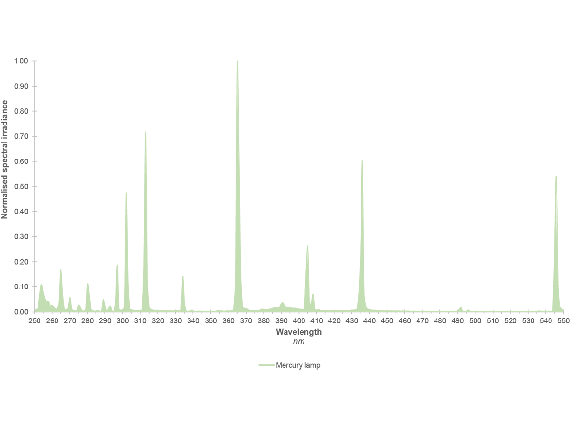
FIGURE 1 » Spectral output charts for mercury and iron.
Lamp is the term used to refer to the UV-emitting quartz tube in Europe and Asia, while North and South Americans tend to use an interchangeable mix of bulb and lamp. Lamp and lamp head both refer to the full assembly that houses the quartz tube and all other mechanical and electrical components.
Electrode Arc Lamps
Electrode arc lamp systems consist of a lamp head, a cooling fan or chiller, a power supply, and a human-machine interface (HMI). The lamp head includes a lamp (bulb), a reflector, a metal casing or housing, a shutter assembly, and sometimes a quartz window or wire guard. GEW mounts its quartz tubes, reflectors, and shutter mechanisms inside cassette assemblies that can be easily removed from the outer lamp head casing or housing. Removing a GEW cassette is typically accomplished within seconds using a single Allen wrench. Because the UV output, overall lamp head size and shape, system features, and ancillary equipment needs vary by application and market, electrode arc lamp systems are generally designed for a given category of applications or similar machine types.
Mercury vapor lamps emit 360° of light from the quartz tube. Arc lamp systems use reflectors located on the sides and back of the lamp to capture and focus more of the light to a specified distance in front of the lamp head. This distance is known as the focus and is where the irradiance is greatest. Arc lamps typically emit in the range of 5 to 12 W/cm2 at the focus. Since around 70% of the UV output from the lamp head comes from the reflector, it is important to keep reflectors clean and replace them periodically. Not cleaning or replacing reflectors is a common contributor to insufficient cure.
For over 30 years, GEW has been improving the efficiency of its curing systems, customizing features and output to meet the needs of specific applications and markets, and developing a large portfolio of integration accessories. As a result, today’s commercial offerings from GEW incorporate compact housing designs, reflectors optimized for greater UV reflectance and reduced infrared, quiet integral shutter mechanisms, web skirts and slots, clam-shell web feeding, nitrogen inertion, positively pressurized heads, touch-screen operator interface, solid-state power supplies, greater operational efficiencies, UV output monitoring, and remote system monitoring.
When medium-pressure electrode lamps are running, the quartz surface temperature is between 600 °C and 800 °C, and the internal plasma temperature is several thousand degrees centigrade. Forced air is the primary means of maintaining the correct lamp-operating temperature and removing some of the radiated infrared energy. GEW supplies this air negatively; this means air is pulled through the casing, along the reflector and lamp, and exhausted out the assembly and away from the machine or cure surface. Some GEW systems such as the E4C utilize liquid cooling, which enables a slightly greater UV output and reduces the overall lamp head size.
Electrode arc lamps have warm-up and cool-down cycles. Lamps are struck with minimal cooling. This allows the mercury plasma to rise to the desired operating temperature, produce free electrons and cations, and enable current flow. When the lamp head is turned off, the cooling continues to run for a few minutes to evenly cool the quartz tube. A lamp that is too warm will not re-strike and must continue to cool. The length of the start-up and cool-down cycle, as well as the degradation of the electrodes during each voltage strike is why pneumatic shutter mechanisms are always integrated into GEW electrode arc lamp assemblies. Figure 2 shows air-cooled (E2C) and liquid-cooled (E4C) electrode arc lamps.
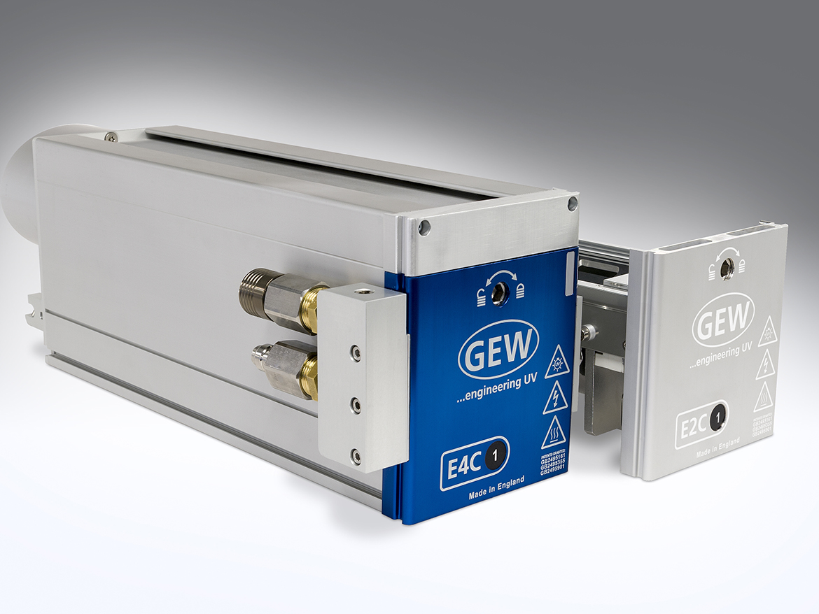
FIGURE 2 » Liquid-cooled (E4C) and air-cooled (E2C) electrode arc lamps.
UV LED Lamps
Semi-conductors are solid, crystalline materials that are somewhat conductive. Electricity flows through a semi-conductor better than an insulator, but not as well as a metallic conductor. Naturally occurring but rather inefficient semi-conductors include the elements silicon, germanium, and selenium. Synthetically fabricated semi-conductors designed for output and efficiency are compound materials with impurities precisely impregnated within the crystal structure. In the case of UV LEDs, aluminum gallium nitride (AlGaN) is a commonly used material.
Semi-conductors are fundamental to modern electronics and are engineered to form transistors, diodes, light-emitting diodes, and micro-processors. Semi-conductor devices are integrated into electrical circuits and mounted inside products such as mobile phones, laptops, tablets, appliances, airplanes, cars, remote controllers, and even children’s toys. These tiny but powerful components make everyday products function while also allowing items to be compact, thinner, light weight, and more affordable.
In the special case of LEDs, precisely designed and fabricated semi-conductor materials emit relatively narrow wavelength bands of light when connected to a DC power source. The light is generated only when current flows from the positive anode (+) to the negative cathode (-) of each LED. Since LED output is quickly and easily controlled and quasi-monochromatic, LEDs are ideally suited for use as: indicator lights; infrared communication signals; backlighting for TVs, laptops, tablets, and smart phones; electronic signs, billboards, and jumbotrons; and UV curing.
An LED is a positive-negative junction (p-n junction). This means that one portion of the LED has a positive charge and is referred to as the anode (+), and the other portion has a negative charge and is referred to as the cathode (-). While both sides are relatively conductive, the junction boundary where the two sides meet, known as the depletion zone, is not conductive. When the positive (+) terminal of a direct current (DC) power source is connected to the anode (+) of the LED, and the negative (-) terminal of the source is connected to the cathode (-), negatively charged electrons in the cathode and positively charged electron vacancies in the anode are repelled by the power source and pushed toward the depletion zone. This is a forward bias, and it has the effect of overcoming the non-conductive boundary. The result is that free electrons in the n-type region cross over and fill vacancies in the p-type region. As electrons flow across the boundary, they transition into a state of lower energy. The respective drop in energy is released from the semi-conductor as photons of light.
The materials and dopants that form the crystalline LED structure determine the spectral output. Today, commercially available LED curing sources have ultraviolet outputs centered at 365, 385, 395, and 405 nm, a typical tolerance of ±5 nm, and a Gaussian spectral distribution. The greater the peak spectral irradiance (W/cm2/nm), the higher the peak of the bell curve. While UVC development is ongoing between 275 and 285 nm, output, life, reliability, and cost are not yet commercially viable for curing systems and applications.
Since UV-LED output is currently limited to longer UVA wavelengths, a UV-LED curing system does not emit the broadband spectral output characteristic of medium-pressure mercury vapor lamps. This means that UV-LED curing systems do not emit UVC, UVB, most visible light, and heat-generating infrared wavelengths. While this enables UV-LED curing systems to be utilized in more heat-sensitive applications, existing inks, coatings, and adhesives formulated for medium-pressure mercury lamps must be reformulated for UV-LED curing systems. Fortunately, chemistry suppliers are increasingly designing offerings as dual cure. This means that a dual-cure formulation intended to cure with a UV-LED lamp will also cure with a mercury vapor lamp (Figure 3).
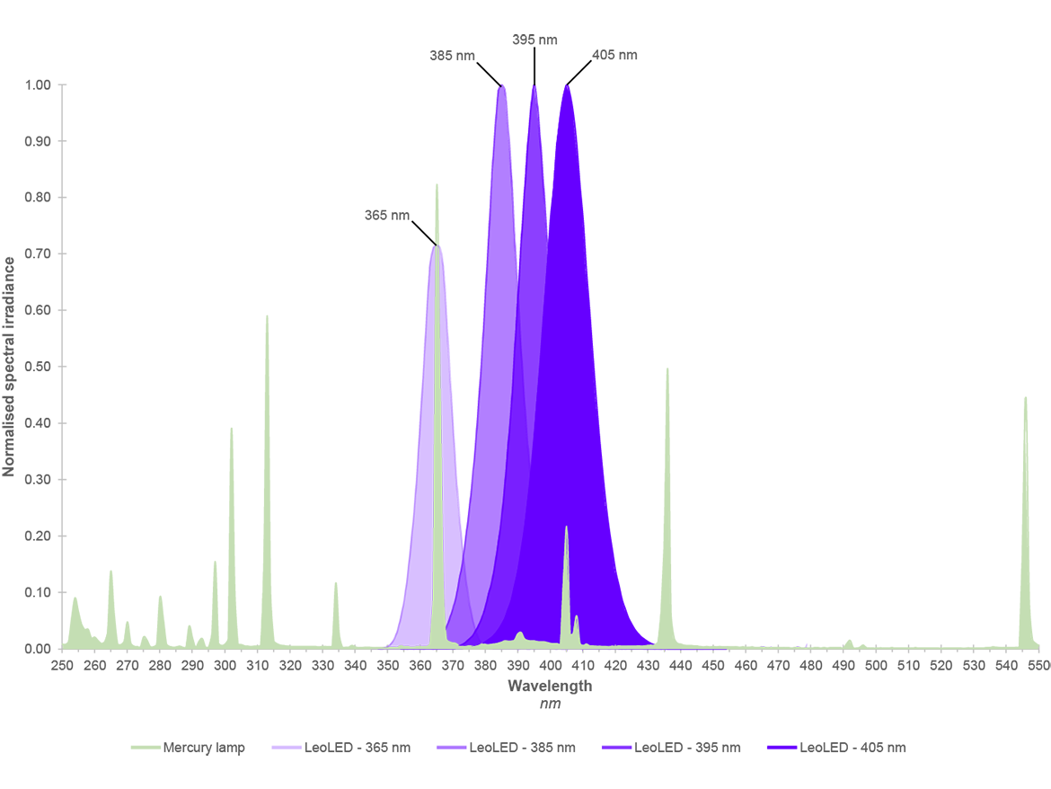
FIGURE 3 » Spectral output chart for LED.
GEW’s UV-LED curing systems emit up to 30 W/cm2 at the emitting window. Unlike electrode arc lamps, UV-LED curing systems do not incorporate reflectors that direct light rays to a concentrated focus. As a result, UV-LED peak irradiance occurs close to the emitting window. The emitted UV-LED rays diverge from each other as the distance between the lamp head and the cure surface increases. This reduces the light concentration and magnitude of the irradiance that reaches the cure surface. While peak irradiance is important for crosslinking, an increasingly higher irradiance is not always advantageous and can even inhibit greater crosslinking density. Wavelength (nm), irradiance (W/cm2) and energy density (J/cm2) all play critical roles in curing, and their collective impact on cure should be properly understood during UV-LED source selection.
LEDs are Lambertian sources. In other words, each UV LED emits uniform forward output across a full 360° x 180° hemisphere. Numerous UV LEDs, each on the order of a millimeter square, are arranged in a single row, a matrix of rows and columns, or some other configuration. These subassemblies, known as modules or arrays, are engineered with spacing between LEDs that ensures blending across gaps and facilitates diode cooling. Multiple modules or arrays are then arranged in larger assemblies to form various sizes of UV curing systems (Figures 4 and 5). Additional components required to build a UV-LED curing system include the heat sink, emitting window, electronic drivers, DC power supplies, a liquid cooling system or chiller, and a human machine interface (HMI).
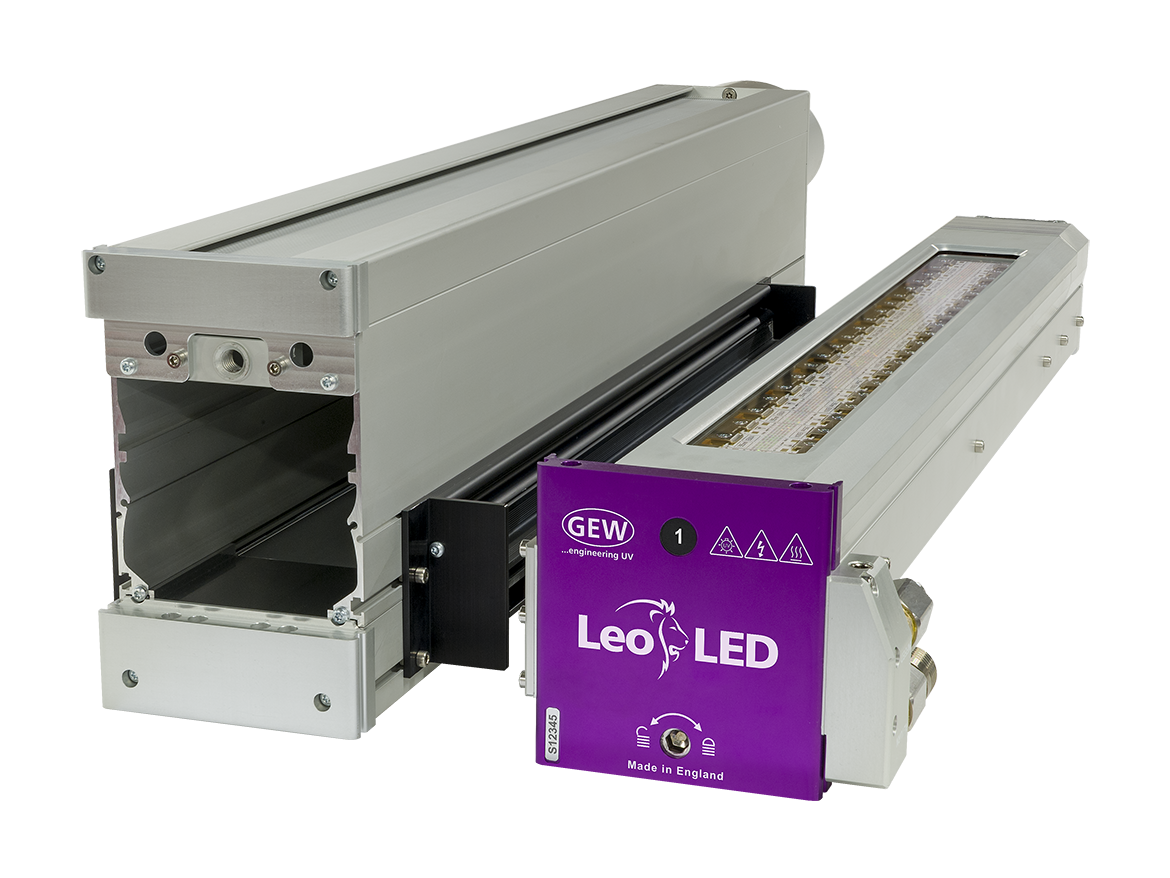
FIGURE 4 » The LeoLED system for web.
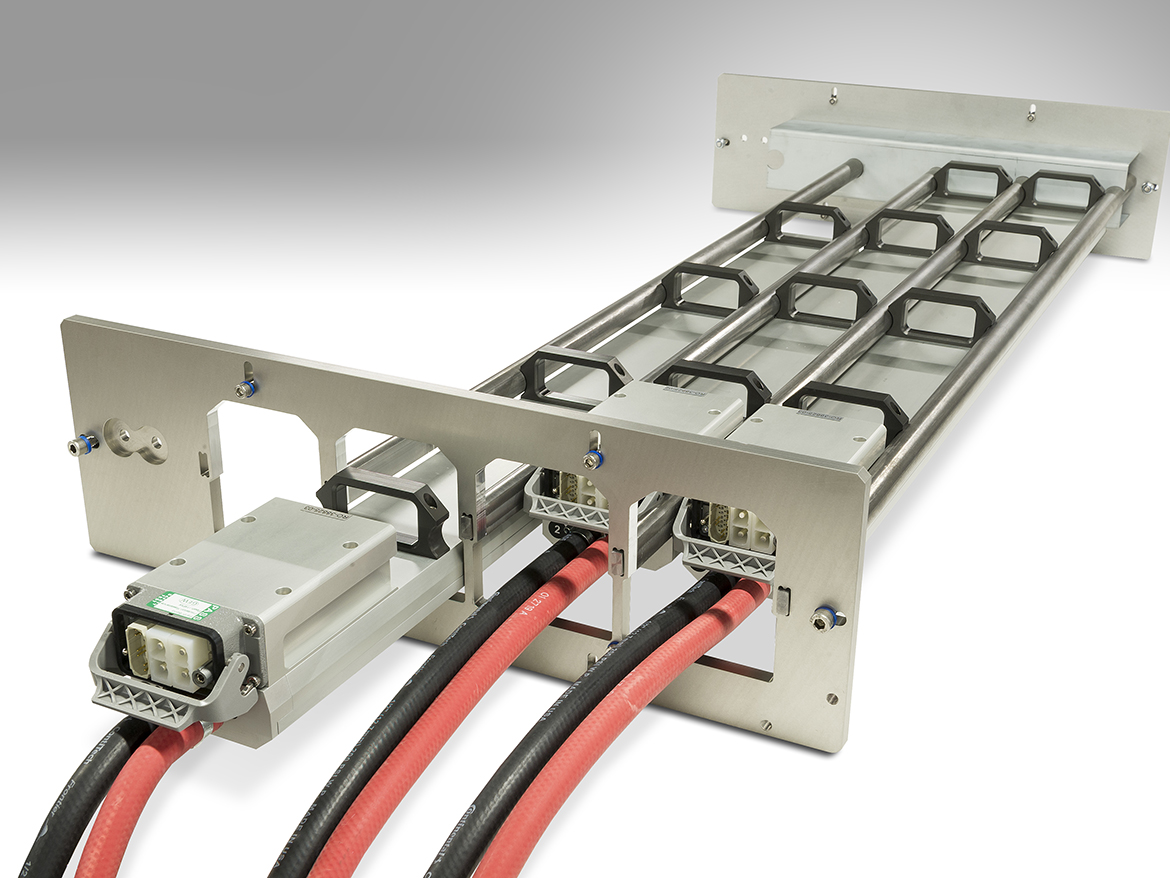
FIGURE 5 » LeoLED system for high-speed multi-lamp installations.
Since UV-LED curing systems do not radiate infrared wavelengths. They inherently transfer less thermal energy to the cure surface than mercury vapor lamps, but this does not mean UV LEDs should be regarded as cold-curing technology. UV-LED curing systems can emit very-high peak irradiances, and ultraviolet wavelengths are a form of energy. Whatever output is not absorbed by the chemistry will heat up the underlying part or substrate as well as surrounding machine components.
UV LEDs are also electrical components with inefficiencies driven by the raw semi-conductor design and fabrication as well as manufacturing methods and components used to package the LEDs into the larger curing unit. While the temperature of a mercury vapor quartz tube must be held between 600 and 800 °C during operation, the LED p-n junction temperature must remain below 120 °C. Only 35-50% of the electricity powering a UV-LED array is converted to ultraviolet output (highly wavelength dependent). The rest is transformed into thermal heat that must be removed in order to maintain the desired junction temperature and ensure specified system irradiance, energy density, and uniformity, as well as a long life. LEDs are inherently long-lasting solid-state devices, and integrating LEDs into larger assemblies with properly designed and maintained cooling systems is critical to achieving long-life specifications. Not all UV-curing systems are the same, and improperly designed and cooled UV-LED curing systems have a greater probability of overheating and failing catastrophically.
Arc/LED Hybrid Lamps
In any market where brand new technology is introduced as a replacement for existing technology, there can be trepidation regarding adoption as well as skepticism of performance. Potential users often delay adoption until a well-established installation base forms, case studies are published, positive testimonials begin circulating in mass, and/or they obtain first-hand experience or references from individuals and companies they know and trust. Hard evidence is often required before an entire market completely relinquishes the old and fully transitions to the new. It does not help that success stories tend to be tightly held secrets as early adopters do not want competitors to realize comparable benefits. As a result, both real and exaggerated tales of disappointment can sometimes reverberate throughout the market camouflaging the true merits of new technology and further delaying adoption.
Throughout history, and as a counter to reluctant adoption, hybrid designs have frequently been embraced as a transitionary bridge between incumbent and new technology. Hybrids allow users to gain confidence and determine for themselves how and when new products or methods should be used, without sacrificing current capabilities. In the case of UV curing, a hybrid system allows users to quickly and easily swap between mercury vapor lamps and LED technology. For lines with multiple curing stations, hybrids allow presses to run 100% LED, 100% mercury vapor, or whatever mix of the two technologies is required for a given job.
GEW offers arc/LED hybrid systems for web converters. The solution was developed for GEW’s largest market, narrow-web label, but the hybrid design also has use in other web and non-web applications (Figure 6). The arc/LED incorporates a common lamp head housing that can accommodate either a mercury vapor or LED cassette. Both cassettes run off a universal power and controls system. Intelligence within the system enables differentiation between cassette types and automatically provide the appropriate power, cooling, and operator interface. Removing or installing either of GEW’s mercury vapor or LED cassettes is typically accomplished within seconds using a single Allen wrench.
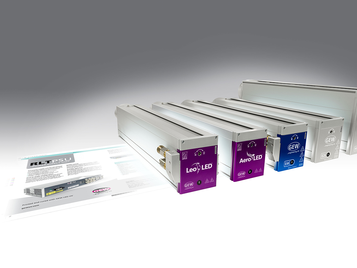
FIGURE 6 » Arc/LED system for web.
Excimer Lamps
Excimer lamps are a type of gas-discharge lamp that emits quasi-monochromatic ultraviolet energy. While excimer lamps are available in numerous wavelengths, common ultraviolet outputs are centered at 172, 222, 308, and 351 nm. 172-nm excimer lamps fall within the vacuum UV band (100 to 200 nm), while 222 nm is exclusively UVC (200 to 280 nm). 308-nm excimer lamps emit UVB (280 to 315 nm), and 351 nm is solidly UVA (315 to 400 nm).
172-nm vacuum UV wavelengths are shorter and contain more energy than UVC; however, they struggle to penetrate very deep into substances. In fact, 172-nm wavelengths are completely absorbed within the top 10 to 200 nm of UV-formulated chemistry. As a result, 172-nm excimer lamps will only crosslink the outermost surface of UV formulations and must be integrated in combination with other curing devices. Since vacuum UV wavelengths are also absorbed by air, 172-nm excimer lamps must be operated in a nitrogen-inerted atmosphere.
Most excimer lamps consist of a quartz tube that serves as a dielectric barrier. The tube is filled with rare gases capable of forming excimer or exciplex molecules (Figure 7). Different gases produce different molecules, and the different excited molecules determine which wavelengths are emitted by the lamp. A high-voltage electrode runs along the inside length of the quartz tube, and ground electrodes run along the outside length. Voltages are pulsed into the lamp at high frequencies. This causes electrons to flow within the internal electrode and discharge across the gas mixture toward the external ground electrodes. This scientific phenomenon is known as dielectric barrier discharge (DBD). As electrons travel through the gas, they interact with atoms and create energized or ionized species that produce excimer or exciplex molecules. Excimer and exciplex molecules have an incredibly short life, and as they decompose from an excited state to a ground state, photons of a quasi-monochromatic distribution are emitted.
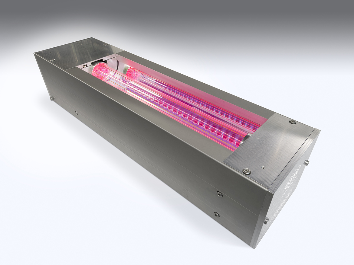
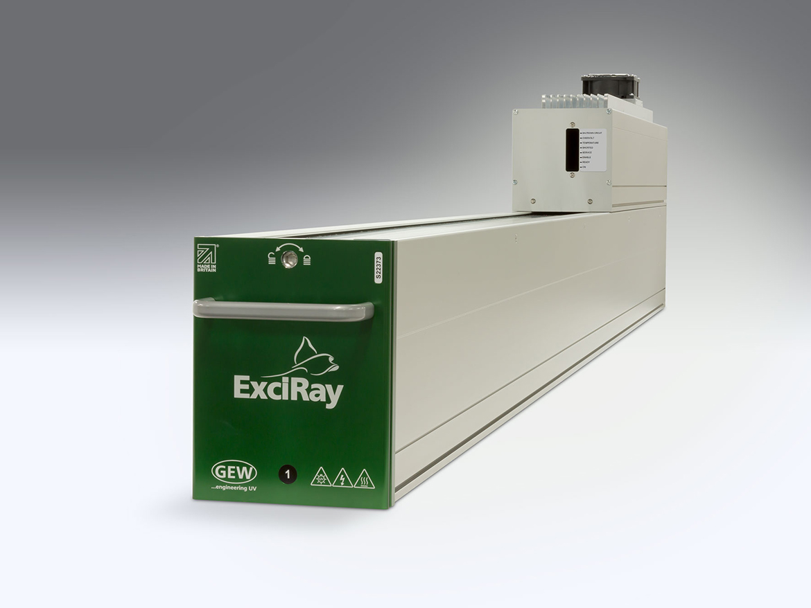
FIGURE 7 » Excimer lamp
Unlike mercury vapor lamps, the surface of an excimer lamp’s quartz tube does not get hot. As a result, most excimer lamps run with little-to-no cooling. In other cases, a low level of cooling is required that is typically provided by nitrogen gas. Due to the lamp’s thermal stability, excimer lamps are instant ‘ON/OFF’ and require no warm-up or cool-down cycles.
When excimer lamps radiating at 172 nm are integrated in combination with both quasi-monochromatic UVA-LED-curing systems and broadband mercury vapor lamps, matting surface effects are produced. UVA LED lamps are first used to gel the chemistry. Quasi-monochromatic excimer lamps are then used to polymerize the surface, and lastly broadband mercury lamps crosslink the rest of the chemistry. The unique spectral outputs of the three technologies applied in separate stages delivers beneficial optical and functional surface-cure effects that cannot be achieved with any one of the UV sources on its own.
Excimer wavelengths of 172 and 222 nm are also effective at destroying hazardous organic substances and harmful bacteria, which makes excimer lamps practical for surface cleaning, disinfection, and surface energy treatments.
Lamp Life
With respect to lamp or bulb life, GEW’s arc lamps generally up to 2,000 hours. Lamp life is not an absolute, as UV output gradually decreases over time and is impacted by various factors. The design and quality of the lamp, as well as the operating condition of the UV system and the reactivity of the formulation matter. Properly designed UV systems ensure that the correct power and cooling required by the specific lamp (bulb) design is provided.
GEW-supplied lamps (bulbs) always provide the longest life when used in GEW curing systems. Secondary supply sources have generally reverse engineered the lamp from a sample, and the copies may not contain the same end fitting, quartz diameter, mercury content, or gas mixture, which can all affect the UV output and heat generation. When heat generation is not balanced against system cooling, the lamp suffers in both output and life. Lamps that run cooler emit less UV. Lamps that run hotter do not last as long and warp at high surface temperatures.
The life of electrode arc lamps is limited by the lamp’s operating temperature, the number of run hours, and the number of starts or strikes. Each time a lamp is struck with a high-voltage arc during start up, a bit of the tungsten electrode wears away. Eventually, the lamp will not re-strike. Electrode arc lamps incorporate shutter mechanisms which, when engaged, block UV output as an alternative to repeatedly cycling the lamp power. More reactive inks, coatings, and adhesives may result in longer lamp life; whereas, less reactive formulations may require more frequent lamp changes.
UV-LED systems are inherently longer lasting than conventional lamps, but UV-LED life is also not an absolute. As with conventional lamps, UV LEDs have limits in how hard they can be driven and generally must operate with junction temperatures below 120 °C. Over-driving LEDs and under-cooling LEDs will compromise life, resulting in more rapid degradation or catastrophic failure. Not all UV-LED system suppliers currently offer designs that meet the highest established lifetimes in excess of 20,000 hours. The better-designed and maintained systems will last beyond 20,000 hours, and the inferior systems will fail within much-shorter windows. The good news is that LED system designs continue to improve and last longer with each design iteration.
Ozon
When shorter UVC wavelengths impact oxygen molecules (O2), they cause oxygen molecules (O2) to split into two oxygen atoms (O). The free oxygen atoms (O) then collide with other oxygen molecules (O2) and form ozone (O3). Since trioxygen (O3) is less stable at ground level than dioxygen (O2), ozone readily reverts to an oxygen molecule (O2) and an oxygen atom (O) as it drifts through atmospheric air. Free oxygen atoms (O) then recombine with one another within the exhaust system to produce oxygen molecules (O2).
For industrial UV-curing applications, ozone (O3) is produced when atmospheric oxygen interacts with ultraviolet wavelengths below 240 nm. Broadband mercury vapor-curing sources emit UVC between 200 and 280 nm, which overlaps part of the ozone generating region, and excimer lamps emit vacuum UV at 172 nm or UVC at 222 nm. Ozone created by mercury vapor and excimer curing lamps is unstable and not a significant environmental concern, but it is necessary that it be removed from the immediate area surrounding workers as it is a respiratory irritant and toxic at high levels. Since commercial UV-LED curing systems emit UVA output between 365 and 405 nm, ozone is not generated.
Ozone has an odor similar to the smell of metal, a burning wire, chlorine, and an electrical spark. Human olfactory senses can detect ozone as low as 0.01 to 0.03 parts per million (ppm). While it varies by person and activity level, concentrations greater than 0.4 ppm can lead to adverse respiratory effects and headaches. Proper ventilation should be installed on UV-curing lines to limit worker exposure to ozone.
UV-curing systems are generally designed to contain the exhaust air as it leaves the lamp heads so it can be ducted away from operators and outside the building where it naturally decays in the presence of oxygen and sunlight. Alternatively, ozone-free lamps incorporate a quartz additive that blocks ozone-generating wavelengths, and facilities wanting to avoid ducting or cutting holes in the roof often employ filters on the exit of exhaust fans.
Post time: Jun-19-2024


